 |
444 MHz
Stacked Dipoles
Designed by VE3ETK |
|
At the
October Meeting Bill VE3ETK gave an excellent talk named "Things You Can
Do With Coax" Here is one project that Bill described. |
This antenna exhibits almost 3db gain and produces a
horizontal dough nut shaped pattern, making it very useful as an outdoor
antenna to increase the signal from your handheld transmitter to local
repeaters. Cost: under $15.00. Time: about 1 ½ hrs.
To make the antenna proceed as follows:
USE ONLY RG-8 COAX WITH STRANDED CENTER WIRE AND WOVEN BRAID SHIELD.
About 6' of this coax is needed.
Approximately 5' of 1" OD PVC pipe, and one end cap
is needed. The end cap needs to be flat (as opposed to rounded) on the
top.
One coaxial cable connector is needed that will fit
RG-8 coax.
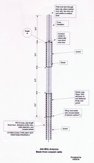 See
attached diagram for assistance. (click on drawing for
full size image suitable for printing) See
attached diagram for assistance. (click on drawing for
full size image suitable for printing)
-
Cut off 10"
of the coax and carefully slice off the outer jacket. Now, carefully
slide back the shield and set it aside.
-
From one end
of the remaining coax (we will hereafter call this the bottom) measure
up 18" and cut through the jacket, all the way around.
-
Measure up a
further 6.5" (all of the remaining measurements are critical to 1/10 of
an inch) and again cut through the jacket all the way around. Remove the
jacket between the two cuts.
-
From ½" UP on
the bared shield cut through the shield, and again at the TOP of this
bared shield. Remove all of the shield between these two cuts.
-
Carefully
fold the ½" of remaining shield back over the jacket, towards the bottom
and secure it with a bare #20 wire. Take the piece of shield you earlier
set aside and carefully slide it up over the coax jacket from the
bottom, until it just covers the ½" of shield just folded back and
secured. Secure this also with a bare #20 wire, and solder the shields
together.
-
Carefully
smooth this section of shield back towards the bottom until it is tight
against the coax jacket. Secure the bottom of the shield with a piece of
tape.
-
Measure from
the top of this section of shield towards the bottom 6.25", and just
barely above that point secure it with a bare #20 wire. Solder the wire
and shield. Just below the wire cut off and remove any surplus shield.
Bind the bottom of the shield section with tape to prevent any 'creep'
upwards.
-
Picking up
now from the top cut made in point 3; Measure up a further 6.5" (this
point will now be referred to as Point A) and remove all jacket from
this point to the top of the coax.
-
1/2" up from
Point A cut through the shield and remove it from that point upward.
Take the ½" of shield and fold it back over the jacket for the moment.
-
At Point A
cut away ¼" of insulation all the way around and right back to the
center conductor. In this ¼" of space, and as close to Point A as
possible, wrap one turn of #18 stranded, bare, wire around the center
conductor and solder in place. Bring the ends of this #18 wire out and
wrap them firmly around the shield that was folded back in 9. Solder as
close as possible to Point A and trim away all excess.
-
From Point A
measure up 6.8" and cut away all insulation from here upward, taking
care not to cut into the center conductor. Measuring up 1" of the center
conductor, cut it off anything beyond that point.
At this time the electronic part of your antenna is
finished.
-
Cut a length
of PVC pipe to slide the antenna down into, leaving enough for a coax
connector at the bottom
-
Push the
center conductor at the top of your antenna through a 1/8" hole drilled
in the center of the top cap. Slide a small brass washer over the bit of
center conductor coming out of the cap. Pull the coax up firmly and
feather the wires of the center conductor out over the washer. Solder
the wires to the washer and cut off any excess.
-
Apply
PVC cement to the top of the pipe and quickly slide this pipe up the
antenna and seat it into the cap.
-
Apply a
liberal coating of epoxy resin to the top of the cap, particularly in
the area of the washer. The whole purpose of the pipe and cap is to give
weather protection to the coax, and to provide a method of mounting.
-
Install the
coaxial connector to the bottom of the coax, and fill the space around
the coax and the bottom of the pipe with weather seal caulking. NOTE: DO
NOT USE SILICONE CAULKING AS IT HAS ACETIC ACID IN IT, AND EVEN THE
VAPOURS FROM THE ACID WILL CORRODE THE COPPER ELEMENTS OF THE ANTENNA.
The antenna is finished, and you may mount it by
using clamps anywhere in the lower 6 inches. I recommend plastic clamps
to prevent any interference with the pattern producing segments of the
coax.
Questions??? Contact Bill VE3ETK at VE3ETK at
RAC dot CA
|